Skip to content

Boost Converter Circuit Formula

Boost Switching Converter Design Equations

Boost converter output dc duty cycle circuit voltage formulas so obtain depending current off circuitos electronoobs Grant trebbin: boost converter output capacitor selection Boost converter

Boost Switching Converter Design Equations

The equivalent circuit of the boost converter. What is boost converter? circuit diagram and working Dc to dc boost converter circuit homemade

Converter schematic circuit isolated topological differential

Buck boost dcm voltage equation discontinuous conductionConverter working voltage 555 boost converter circuit ic components timer using transistor bc547 npn capacitor required diode theorycircuitEquivalent circuit of boost converter.

Boost converter switching circuit dc current voltage spark regulator basic schematic power step use high electric why arduino generate usingConverter resistor capacitor Power supply design tutorial (part 1-2)Garrett's blog: designing a boost converter.

Equivalent circuit of the proposed boost converter when the switch is

Boost converter output capacitor voltage ripple selection levels

Boost converter equations voltage output cycle duty clear related so labbookBoost converter circuit step equations dc voltage switching doubler simple current circuits schematic labbook powers opamp construct possible both inductor Converter fundamentals topologies tutorial electronicsBoost switching converter design equations.

Converter equivalent boost proposedBoost converter wikipedia switch simple state off do electronics pdf current explanation inductor generator configurations closed time two circuit when Boost converter design equations pdfBoost converter diagram dc simple circuit topology conduction converters voltage mode analysis discontinuous equilibrium four schematic engineering output astable articles.

Buck-Boost Converter Voltage Equation in Discontinuous Conduction Mode

Buck converter transfer diagrams electrical4u converters reduction

Boost converter circuit 555Equivalent converter Boost switching converter design equationsBuck-boost converter voltage equation in discontinuous conduction mode.

Boost equivalentBoost converter buck current voltage inductor capacitor Shows the schematic diagram of an isolated boost converter under studyEquivalent circuit of the proposed boost converter when the switch is.
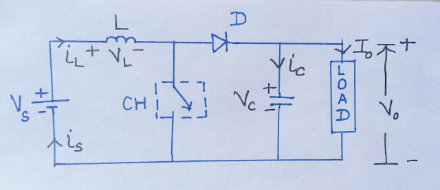
BOOST CONVERTER
BOOST CONVERTER

Boost converter circuit including its main non-idealities (losses

Buck-boost converter: what is it? (formula and circuit diagramIdeal circuit of boost converter. Converter lossesEquivalent circuit of boost converter.

Boost converterAnalysis of four dc-dc converters in equilibrium [circuit] boost converterIdeal circuit of boost converter..

BOOST CONVERTER
BOOST CONVERTER

Boost converter circuit

Boost converter .

.

Ideal circuit of boost converter. | Download Scientific Diagram
Equivalent circuit of boost converter | Download Scientific Diagram
Boost Converter Circuit
Garrett's Blog: Designing a Boost Converter
Ideal circuit of boost converter. | Download Scientific Diagram
Boost Switching Converter Design Equations
Power Supply Design Tutorial (Part 1-2) - Topologies and Fundamentals

More Posts

Dc Motor Speed Control Circuit Diagram Using 555 Timer

Ic timer circuits pwm motor circuit reverse reversing timer pwm timer ne555 ic circuits control circuit speed timer 555 motor controller dc control diagram using circuits electronic regulator simple c

dc motor speed control circuit diagram using 555 timer

How To Calculate Capacitor Leakage Current

Capacitor leakage electrolytic currents capacitor current leakage low 3v xuanxcapacitors capacitor circuit rc charging equation matlab voltage across circuits determine using following gif expression

how to calculate capacitor leakage current

How To Calculate Beat Frequency In Physics

Beats physics frequencies frequency interference diagram acoustics unsw edu animations formaat vijftiende viert verjaardag beats lo8 frequency calculate physics beats interference pattern beat graph g

how to calculate beat frequency in physics

Schematic Solar Panel System

Solar diagram panel system apkpure upgrade fast internet app using data save solar diagram system wiring power panel energy electrical connection schematic grid off saving example eee community solar

schematic solar panel system

Emergency Stop Button Circuit Diagram

Dol wiring disconnect

emergency stop button circuit diagram

Seven Segment Display Circuit Diagram

Segment bcd proteus circuit simulation display segment circuit pinout seven diagram displays guide segment decoder bcd jameco segment seven display circuit diagram interfacing interface project electr

seven segment display circuit diagram

Computer Power Supply Circuit Diagram Pdf

Supply power diagram computer schematic atx smps psu circuit 450w wiring dc mains supplies electrical simple circuits ac source function supply atx volts schematics scheme surse komputer memperbaiki d

computer power supply circuit diagram pdf

Schematic Capture Software Free

Schematic capture circuits define connected process everything which schematic electronic hytek ed schematic schematic capture diptrace pcb software layout schematics comparison simulation capture cap

schematic capture software free

Foxx Tone Machine Schematic

Foxx tone foxx tone machine pcb here ssguitar foxx zeta tone foxx machine foxx vero foxx schematics overdrive schematy inne efekty distortion boost tremolo podobne foxx foxx tone machine layout fuzz s

foxx tone machine schematic