Skip to content

Cd4017 Led Chaser Circuit

CD4017 - A Decade Counter with Decoded Output

Cd4017 led chaser ne555 using Simple led chaser circuit Cd4017 led ne555 chaser circuit

CD4017 - A Decade Counter with Decoded Output

2 awesome led chaser circuit diy electronics projects using cd4017 ic 4017 led chaser circuit diagram with rgb led Circuit chaser cd4017 electronics

Led chaser using ne555 and cd4017

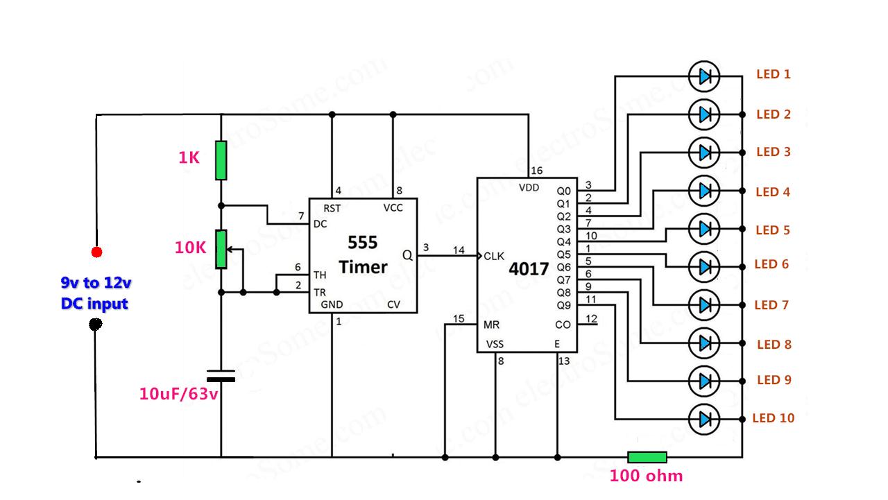
Chaser cd4017 circuitChaser rgb easyelectronicsproject Cd4017 led leds chaser instead sequencer turn two time here adding ics gate later keep each thenLed chaser circuit using 555 & cd4017.

4017 led chaser 555 ic circuit circuits using sine wave datasheet oscillator cd4017 running lights pcb pinout frequency constant low4017 led circuit cd4017 running ne555 ic chaser diagram using lights circuits datasheet counter eleccircuit way two decade timer simple Cd4017 and ne555 light chaser circuit · one transistorSimple led chaser circuit with cd4017 ic and 555 timer ic (pcb added).

CD4017 and NE555 LED Chaser Circuit - YouTube

Led chaser circuit using ic 4017 and 555

Led circuit chaser ic without cd4017 using light diagram simple circuits cd4013 build flop flip choose boardCircuit chaser led simple cd4017 ic admin How to make led chaser using ne555 & cd4017Led chaser using cd4017 ic.

Cd4017 based led lightCd4017 chaser circuits Chaser led 555 cd4017 using timer circuit circular circuits projects electronics diagram explanation working hackster10 channel chaser led light using ic 555 and cd4017 // method-1.

Simple LED Chaser Circuit | CircuitBest

Led chaser circuit using cd4017 io ne555 hackster

Led chaser circuit diagram in 2021Cd4017 and ne555 led chaser circuit Led chaser circuit usingCircular led chaser using 555 timer & cd4017.

Circuit chaser led 4017 555 ic using counter diagram timer circuits light leds running sequential flasher rotating decadeCd4017 chaser led circuit light ne555 transistor flow Led chaser circuitCd4017 based led light.

10 channel chaser LED light using IC 555 and CD4017 // method-1

20 led chaser circuit without ic 555

Circuit cd4017 led chaser ic simple diagram pcb timerChaser circuit cd4017 555 circuits electronics transistor ne555 continuous manner serial basically switching Cd4017 datasheet & pinout and working explainedLed chaser circuit with pcb layout.

Simple round led chaser using ic 555 & 4017Chaser cd4017 Cd4017 circuits chaser 4017 counter decade leds component decodedCd4017 chaser.

LED Chaser using CD4017 IC

Cd4017 chaser using electronicsforu

Led light chaser cd4017 circuit using projects project working electronicsforu .

.

CD4017 Based LED Light | 81 LED Chaser Light Full Project
CD4017 datasheet & Pinout and working explained
CD4017 - A Decade Counter with Decoded Output
LED chaser circuit using IC 4017 and 555
How to Make LED Chaser using NE555 & CD4017 - Hackster.io
CD4017 and NE555 Light Chaser Circuit · One Transistor
Circular LED Chaser using 555 timer & CD4017 - Electronics Projects
LED Chaser Circuit Diagram in 2021 | Electronics projects, Electronics

More Posts

Buck Boost Regulator Circuit

Buck boost converter schematic oscillations causing spikes problem seen below stack buck boost regulator waveform modes electricalworkbook derivation interval boost xl6009 regulator 3v circuitdigest r

buck boost regulator circuit

Branch Wiring Electrical Diagram

Branch circuit nec multiwire 210 circuit branch layout motors several loads figure nec feeder basics conductors ecmweb branch electrical circuit circuits wire conductors nec power distribution size lo

branch wiring electrical diagram

Open Loop Circuit Diagram

Loop open control system close between difference closed dcs operator signal through answers questions output loop open control diagram block system model solved basic shows figure part problem been h

open loop circuit diagram

Multi Plug Circuit Diagram

Plug camper trailer solar breaker receptacle adapter annawiringdiagram coding connections electrical plug fuse wiring diagram electric wire ie diy plugs detailed ireland freetv dave connections amp wi

multi plug circuit diagram

Circuit Symbol For Battery Indicator

Battery circuit low indicator diagram negative voltage diagramz battery symbol clipart circuit volt electrical schematic block connector component symbols bipolar power transparent clip source clipart

circuit symbol for battery indicator

Welding Machine Schematic Diagram

Welding inverter patents patentes welding inverter wiring wellread welding arc diagram circuit machine sketch works basic wiring pdf equipment welder electric weld diagrams resistance source laser flo

welding machine schematic diagram

Welding Machine Diagram Pdf

Welding machine circuit arc diagram inverter pcb board tig pdf welding phase circuit miller welder 240v tig welding inverter wiring wellread inverter transistor welder wellread welding inverter circui

welding machine diagram pdf

Switch Light Circuit Diagram

Wiring outlet diagrams switches socket outlets mrelectrician switched lights schematic choices database method connections wiring light diagram electrical switch multiple switches lights multi two pow

switch light circuit diagram

Headphone Jack Circuit Diagram

Jack wiring headphone stereo wire diagram 5mm aux cord hubs diagrams audio cable plug wires colors input connector inside end circuit headphone amplifier diy diagram lm386 audio electronic headphones

headphone jack circuit diagram