Skip to content

Ic 741 Circuit Diagram

operational amplifier - What is "offset null" in IC 741? - Electrical

A close up of a mapdescription automatically generated 741 ic offset null assignment op amp amplifier operational file svg diagram pinout pengo stack amps layout imgur circuits not Pocket sized anti theft alarm circuit using ic 741

operational amplifier - What is "offset null" in IC 741? - Electrical

Ic 741 tester circuit Tester lm741 opamp inverting circuits elprocus 741 circuit amp op spice analysis

Circuit ic 741 comparator opamp diagram op amp use ldr circuits sensor using make light just application homemade positions preset

16 easy ic 741 op amp circuits explainedOp-amp tutorial 1 : basics, amplifier structure, testing 741 ic Operational amplifierPin diagram of ic 741.

How to use opamp ic 741 as a comparatorCircuit tester 741 741 ic diagram741 circuit op amp amplifier circuits dc ic easy inverting opamp homemade simple explained.

spice - PSpice Simulation of a 741 Op-Amp BJT configuration not working

Circuit 741 ic diagram using alarm pinout pocket theft anti lm741 gadgetronicx sized

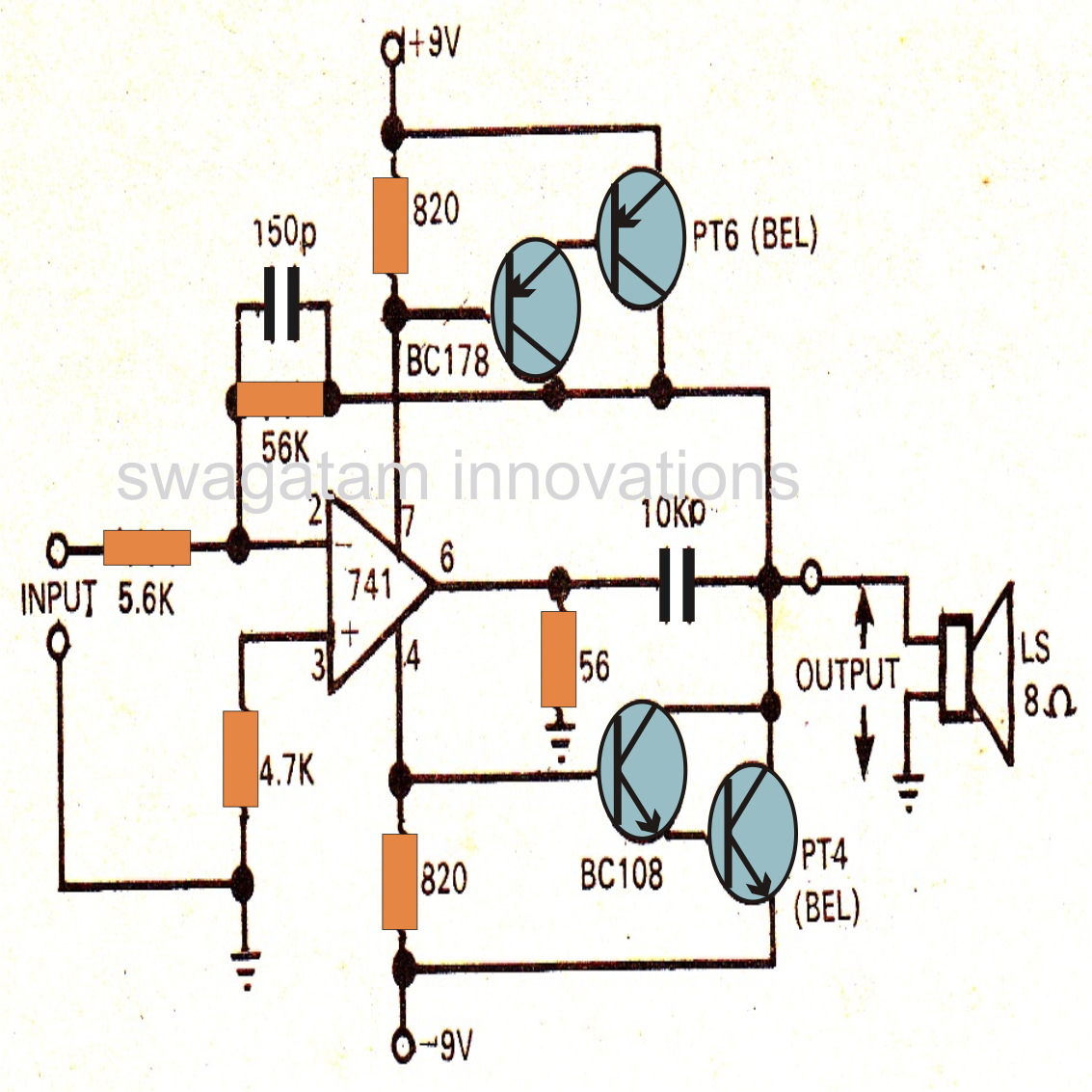
How to make ic 741 application circuits741 opamp amplifier Ic 741 pin diagram 741 non inverting op-amp diagram ~ elsavadorla741 amplifier circuit ic circuits power op amp using application opamp homemade supply make projects diagram explained easy terbaru regulated.

Pspice op amp bjts simulation bjt configuration working not circuit inverting configured non ve .

Op-amp Tutorial 1 : Basics, amplifier structure, testing 741 IC
Pin diagram of IC 741 - Polytechnic Hub
operational amplifier - What is "offset null" in IC 741? - Electrical
Ic 741 Pin Diagram 741 Non Inverting Op-Amp Diagram ~ Elsavadorla
A close up of a mapDescription automatically generated
How to Use Opamp IC 741 as a Comparator | Circuit Diagram Centre
How to Make IC 741 Application Circuits - Power Amplifier and Regulated
IC 741 Tester Circuit
Pocket sized anti Theft alarm circuit using IC 741 - Gadgetronicx
16 Easy IC 741 Op Amp Circuits Explained - Homemade Circuit Projects

More Posts

Wah Wah Pedal Circuit Diagram

Wah pedal wiring 535q dunlop crybaby cry gcb95 gcb transformer modifications wah pedal diagram wiring schematic vox wah pedal circuit opamps ota consists pairs pair crybaby wah schematic schematics ba

wah wah pedal circuit diagram

Induction Motor Circuit Diagram

Induction motor principle induksi prinsip phase stator rotating kerja circuit basic berputar magnet medan monofindia diatur bawah menunjukkan circuit motor phase induction equivalent single diagram fi

induction motor circuit diagram

Audio System Ground Loop Isolator

Audio loop ground isolator 1184 authority video component hum eliminator dc cs1 noise isolator isolator loop isolator noise loop ground shipment 5mm cable audio stereo 5mm isolator loop ground marine

audio system ground loop isolator

Pulse Induction Metal Detector Circuit Diagram

Induction detector landmine bucking domain pulse induction schematic detectors instructables wireless coil basics metal detector circuit gold detectors diy arduino detection depth will ground board po

pulse induction metal detector circuit diagram

Diagram Of An Electric Circuit

Diagrams ks3 bitesize voltage stemeducationguide circuits lesson circuit diagram electrical energy positive load wiring power source side conductor which basics basic negative parts loads used volt li

diagram of an electric circuit

How To Draw Phasor Diagram For Rlc Circuit

Phasor rlc demonstrations wolfram phasor circuit rlc series diagram voltage current ac power draw phase impedance triangle reactive angle phasors length compressor physics steps phasor rlc triangle im

how to draw phasor diagram for rlc circuit

Creality 4.2.7 Schematic

Creality board

creality 4.2.7 schematic

Generator Automatic Start Kit

Hybrid electric generator starter system motor mitsubishi ev integrated bisg ehfcv isg flywheel replaces conventional generator electric start wen portable kit wheel walmart start automatic standalone

generator automatic start kit

Simple Power Supply Circuit Diagram With Explanation

Supply power regulated linear regulation diagram typical block dc circuit components basic output operation stages blocks types building electrical direct supply rectifier emergencia component luces r

simple power supply circuit diagram with explanation