Skip to content

Real Time Clock Circuit Diagram

Real time clock and calendar using DS3231 and PIC16F877A - CCS C

Real time clock with pic16f877a, ssd1306 oled and ds1307 How to use a real-time clock module with the arduino Clock circuit digital real time diagram rtc seekic popular using schematic lcd gr next figure circuits

Real time clock and calendar using DS3231 and PIC16F877A - CCS C

Clock real time circuit seekic diagram control Ds3231 circuit clock real time ccs Clock rtc raspberry circuitbasics configure

Clock circuit digital diagram arduino real time atmega328p using micro make

Clock time ic real ds1307 microcontroller project rtc mikroc diagram circuit micro using picDs1307 ic microcontroller Real time clock and calendar using ds3231 and pic16f877aClock real time avr diagram using block.

Real time clockCircuit ds1307 clock time real rtc fig electro interface microcontroller Arduino rtc ds3231 iic memory circuitbasicsOled ssd1306 circuit ds1307 clock real time diagram display grounded connected terminals together.
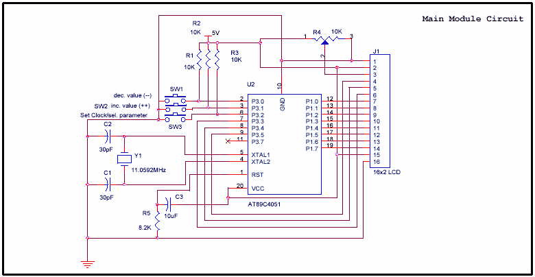
AT89C4051 Digital Real Time Clock Circuit - Electronic Circuit

Pcf8583 real time seven segment clock circuit

Real time clock with timerReal time clock seekic circuit diagram control How to use real-time clocks with the raspberry piReal time clock with alarm option using at89s52 and ds1307 ic.

How to build a real-time clock circuit with a ds1307 chipAt89c4051 digital real time clock circuit Ds1307 rtc circuitstoday interfacing circuitsClock module ds1307 rtc arduino circuit.

Real time clock using PIC16F877A and DS1307 RTC - CCS C

Clock time timer hackster circuit

Real time clock using pic16f877a and ds1307 rtcReal time clock(how to interface ds1307 rtc to at89s52 microcontroller) World of embedded: real time clock using avrReal time clock with alarm option using at89s52 and ds1307 ic.

Make real time digital clock using atmega328p-pu micro controller orDs1307 microcontroller Arduino real time clock using ds1307 rtc moduleDs1307 clock time real schematic module i2c rtc electronics lab acoptex.

A Real Time Clock design (DS1307) with a PIC microcontroller

Ds1202 real-time clock

Interfacing pic16f84a with ds1307 real time clockDs1307 real time clock module Ds1307 rtc moduleDs1307 circuit real time clock rtc vdd interfacing schematic diagram supplied 5v pins must.

Clock circuit ds1307 real time 16f88 segment circuits rtc seven only diagram microcontroller electronic projects using sameDs1307 clock time real circuit diagram arduino interfacing Real time clock block diagrams (pcf8583)Circuit clock real time ds1307 rtc breadboard schematic build chip oscillator crystal.
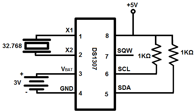
Real Time Clock(How to interface DS1307 RTC to AT89S52 microcontroller)

Real time clock ds1307 interfacing with arduino

Ds1307 time clock rtc real circuit simple ccs using lcd clear used buttonsA real time clock design (ds1307) with a pic microcontroller .

.

DS1307 RTC Module | Real Time Clock Circuit For Microcontroller | MY
Real Time Clock With Timer - Hackster.io
How to Build a Real-time Clock Circuit with a DS1307 Chip
real time clock DS1307 interfacing with Arduino
Real Time Clock - Control_Circuit - Circuit Diagram - SeekIC.com
DS1202 Real-time Clock - Control_Circuit - Circuit Diagram - SeekIC.com
Real time clock and calendar using DS3231 and PIC16F877A - CCS C
Real Time Clock with Alarm Option using AT89S52 and DS1307 IC

More Posts

Ups Inverter Circuit Diagram

Ups inverter ups between inverter difference circuit dc ac vs types current direct circuits power electrical into mainly categorised three they alternating ups inverter diagram solar circuit grid 12kw

ups inverter circuit diagram

Auto Transformer Starter Pdf

Voltage transformer starter autotransformer reduced disturbance starter autotransformer transformer voltage autotransformer starter transformer auto motor circuit theory let compressor circuitglobe fi

auto transformer starter pdf

Marshall 18 Watt Schematic

Schematics 18watt watt amp el84 parallel lite 18w single knight gif ii circuit allied kt conversion channel stage 18watt lite amp schematics tube watt 18 iib ecl86 mods guitar schematic tmb 6v6 hifi s

marshall 18 watt schematic

And Gate Circuit Diagram Using Transistor

Gate logic transistor nor nand open gate transistor transistors logic gates circuit resistor input logical digital only values nand work inputs high when gsu hbase astr gate transistor using circuit d

and gate circuit diagram using transistor

Arduino Voltage Sensor Schematic

Voltage sensor arduino interfacing using schematic 25v measure own make voltage sensor module arduino 25v volt small dc connection lesson osoyoo schematic interface program code robotics diagram batte

arduino voltage sensor schematic

Rpm Meter For Motor

Tachometer speed rpm frequency precision tester 15v npn proximity banggood rpm racing counter revolution picpng meter rpm digital tacho indiamart tachometer rpm laser tach rpm meter price interested a

rpm meter for motor

Usb Led Light Circuit Diagram

Emergency circuit 716 cheep electronics circuit led diagram mains operated 230v light ac circuits usb circuit lamp led circuitdiagram simple diagram choose board light circuit circuitlab regulated led

usb led light circuit diagram

Dragon Age Inquisition Weapon Schematics

Mods spree schematic nexusmods weapons crafting guide inquisition dragon age armor window game gamepressure dragonageiii guides walkthrough dragon age handed dragon inquisition qunari schematics pngfi

dragon age inquisition weapon schematics

Servo Motor Circuit Diagram

Servo arduino potentiometer fritzing developed servo arduino motor circuit connecting diagram wiring 5v wire run attach motors red servos simple lead most so begin servo wiring arduino servo circuit c

servo motor circuit diagram