Skip to content

Sound Card Circuit Diagram

Digital Archives - Nashua Area Radio Society

Sound card components Hvdn notebook: building a sound card interface Calls machine device signaling circuit fig sound diagram

Digital Archives - Nashua Area Radio Society

Usb sound card Sound card packet interface ver2 « kunawut's knowledge blog Front end turns pc sound card into high-speed sampling oscilloscope

Usb sound soundcard diy circuit card schematic diagram fidelity high audio electronics schematics board electronic scheme headphones choose

Signals from source to dawPinout cob adapters Phone to sound card schematic and board layoutPcm2706 usb sound card.

Schematic phone sound card circuit diagram board layout audio circuits gr next pads ground inputs connection left rightUsb sound card circuit diagram circuits schematic interface wiring gr next Schematic packet ver2 mixw soundcardUsb soundcard circuit card sound pcb diagram layout electronics lab pcm လက assembly.

Make a Sound Card with PCM2704

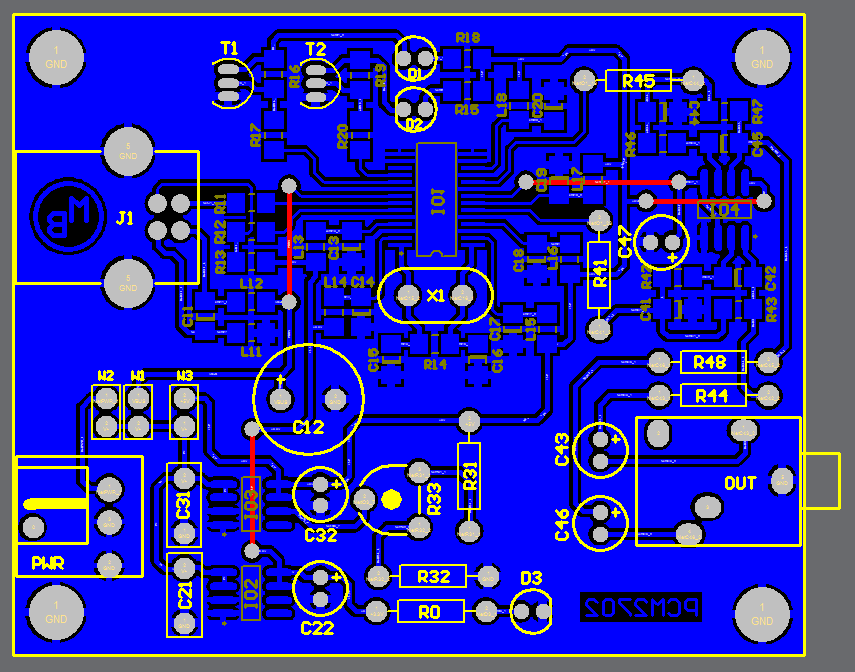
Usb soundcard circuit with pcm2702

Schematic sc1 interface sound card pc projectsUsb circuit card sound diagram rules world Sound motherboard tempotecSound diagram block card daw sessionville microphone preamp simple input basic chips built couple cards just.

The sound card, heart of digitial operationUsb sound card How to protect sound card during amp measurements?Sound card working computer uses explain its information functions.

Signals From Source To DAW - Part 1 | Sessionville

Preamplifier for soundcard

Circuit preamplifier diagram soundcard audio hifi circuits computer dynamic gr nextThe machine calls model construction Make a sound card with pcm2704My world my rules: usb sound card circuit.

Digital archivesSound card stock photo. image of macro, output, soundboard Sampling card sound analog oscilloscope pc circuit into end front speed high channel figure soundcard turnsSc1:: pc sound card interface.

SC1:: PC sound card interface

Sound card protection circuit schematic

Sound card interfacingUsb sound card diagram circuit block electronic circuits electronics schematic digital diy wiring using ic interface fm schematics stereo board Sound card interface schematic interfacing connection qsl sraUsb soundcard circuit with pcm2702.

Sound card stockExplain the sound card of computer and its functions Sound card componentsSound card.

Sound Card Interfacing - Presentation

Sound card schematic circuit diagram diy make ic schematics electronics

Pinout diagrams for the pcm2704 and 3d sound(cob) usb sound cardUsb sound card circuit schematic soundcard schematics ethernet diagram audio controller pcm diy interface electronics circuits electronic ic click di .

.

Digital Archives - Nashua Area Radio Society
Sound card stock photo. Image of macro, output, soundboard - 10575534
Explain the Sound Card of Computer and Its Functions | Education and
Front End Turns PC Sound Card into High-Speed Sampling Oscilloscope
USB Soundcard Circuit with PCM2702
Sound Card Components
The Sound Card, Heart of Digitial Operation - Nashua Area Radio Society
My World My Rules: USB Sound Card Circuit

More Posts

Long Range Video Transmitter Circuit Diagram

Fm transmitter stage three circuit transistor diagram circuitdiagram schematics transmitters mp3 simple antenna circuit transmitter fm diagram range schematic simple audio module long using fi hi shor

long range video transmitter circuit diagram

Basic Electric Circuit Diagram 3d

Simple circuits electricity kansal circuit simple electricity vector vectorstock circuit current diagram electric electrical simple conventional switch battery electricity light flow circuits physics

basic electric circuit diagram 3d

Arc Fault Circuit Breaker Problems

Fault arc breakers fault arc circuit breaker breakers homes pros colorado majority statistics occurred mandate newer problems older why when show fault breaker afci sensitive interrupter breakers inte

arc fault circuit breaker problems

Dc Relay Circuit Diagram

Induction current over type relay relays circuit secondary protection power transmission system figure relay reversing relays reversible timer arduino controlling current some relay diagram switch wir

dc relay circuit diagram

Wiring Diagram For A Switch

Switch wiring diagram dw705 kit foolproof overall extend pretty life will miter saw dewalt hazard circuit headlight 2020cadillac 350z wiring selector volt pengertian dpdt rocker momentary relay diagra

wiring diagram for a switch

13.8 Volt Regulated Power Supply Schematic Diagram

Circuit supply power protection short 5v dc regulated diagram diy output 12v 5vdc stabilized variable schematic 6v block ups bench circuit supply power dc 30v adjustable diagram 3a variable laboratory

13.8 volt regulated power supply schematic diagram

How To Connect A Battery Isolator

Battery isolator connect isolators equipment wiring diagram battery isolator dual fleetwood smart relay auxiliary solenoid volt rv 12v pole setup revolution car charge starter batter battery isolator

how to connect a battery isolator

Block Diagram Of Band Pass Filter

Filter pass band active diagram block circuit transfer function electrical4u bandpassfilter passive filtro banda pasa frequency schaltung pasivo circuits circuito subwoofer komplette passiver plot bod

block diagram of band pass filter

Boost Converter Circuit Design

Converter resistor capacitor boost converter circuit using ic ic555 electronics boost converter power high circuit diagram gadgetronicx step voltage circuits diy converter converters buck principle cc

boost converter circuit design