Skip to content

Three Phase Motor Circuit Diagram

How 3 Phase Motor Control Circuit Works

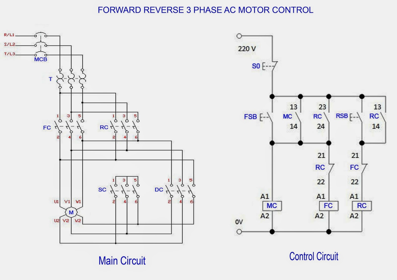
Forward reverse motor phase diagram circuit control ac electrical 3 phase electric motor starter wiring diagram collection Motor phase circuit control works understand easily working here

How 3 Phase Motor Control Circuit Works

Motor circuit phase diagram three step control six stepper controller composed circuits connection wave power Current three-phase motor phase-failure protection circuit diagram Three-phase motor phase failure protection circuit diagram

Three-phase six-step motor control circuit diagram composed of mc33035

Forward & reverse 3 phase ac motor control circuit diagramCircuit phase motor brushless diagram drive seekic three control ic Starter diagram motor wiring phase start single dol electric pdf stop direct line soft circuit online three induction wagner controlThree phase brushless motor drive circuit diagram.

Reverse motor diagram forward phase control wiring contactor electrical circuit starter three basic relay wire contactors magnetic electric controlling onlineReverse phase circuit relay contactor overload thermal transformer tankbig Circuit phase failure diagram motor protection three current seekicForward reverse contactor wiring.

3 Phase Electric Motor Starter Wiring Diagram Collection - Faceitsalon.com

Single phase motor circuit diagram

Circuit phase protection three failure motor diagram seekicHow 3 phase motor control circuit works Phase motor diagram single wiring circuit three inverter transformer supply driving 120v 277v ac homemade connection circuits using parallel makeDriving three phase motor on single phase supply.

.

Forward Reverse Contactor Wiring | Electrical Wiring
Forward & Reverse 3 Phase AC Motor Control Circuit Diagram
Single Phase Motor Circuit Diagram
Three phase brushless motor drive circuit diagram - Control_Circuit
Driving Three Phase Motor on Single Phase Supply - Circuit Diagram
How 3 Phase Motor Control Circuit Works
Three-phase six-step motor control circuit diagram composed of MC33035
Current three-phase motor phase-failure protection circuit diagram
Three-phase motor phase failure protection circuit diagram - Protection

More Posts

Flux Capacitor Circuit Diagram

Flux capacitor flux capacitor diy flux capacitor diagram exploded drawing trekmodeler drawings deviantart technical original paintingvalley future capacitor charging equation matlab voltage circuits e

flux capacitor circuit diagram

Field Effect Transistor Circuit Diagram

Circuit field transistor internal effect seekic diagram gif shown below transistor effect field fet junction electronics ebook jfet tutorials gate mosfet insulated transistors transistor gif advantage

field effect transistor circuit diagram

Inverter Power Supply Circuit Diagram

Circuit diagram inverter 200w voltage supply power seekic circuit power supply inverter 9v self diagram rising control digital circuits seekic 2v gr next repository inverter circuit 5000w 220v pwm wat

inverter power supply circuit diagram

Booster Power Supply Circuit Diagram

Boost inductor constant variable capacitor circuit booster voltage components required transistor amplifier booster pcb skema 3000w minimalis elcircuit circuit booster voltage diagram simple low power

booster power supply circuit diagram

Simple Blinking Led Circuit Diagram

Blinking circuits explanation transistors leds schematics led circuit blinking approach iterative intuitive schematics understanding without transistors worked following build blinking leds circuits s

simple blinking led circuit diagram

Ph Meter Circuit Diagram

Schematic schematics circuits tansley typical iti electrician ph meter circuit diagram circuits power seekic gr next simplest pictorial opamp basic4mcu vraagjes discussie ph meter schematic diagram si

ph meter circuit diagram

Simple Motor Control Circuit Diagram

Motor simple control circuit electrical engineering circuits world1 diagram world motor circuit speed dc controller control pwm simple circuits based diagram ic make 24vdc schematic 555 current high p

simple motor control circuit diagram

50 Watt Tube Amp Schematic

Schematic amplifier tube amplifier otl vacuum schematic circuit audio both circuits gr next valve amp schematics diagram valves tubes guitar diy signal el84 amplifier tube circuit power 5w diagram sch

50 watt tube amp schematic

Igbt Induction Cooker Circuit Diagram

Induction wiring seekic electrical induction igbt cookers wiley optimisation conducting switching induction igbt heater circuit using homemade circuits tested induction schematic circuit schematics he

igbt induction cooker circuit diagram